
In Part 1 of this series, we made the case that solar ROI is tied to performance, not price, and we showed you exactly what happens when that principle is ignored. The 177 kW plant at the Caffeine and Tea Exporter factory in Bagru, Rajasthan, was generating barely half of what it should have been. The inverter was tripping 7 to 8 times per day. Missing documentation. No surge protection. Open, exposed cables without conduits. A system that looked complete on the outside and was failing systematically on the inside.
The factory owner had paid for 177 kW. They were getting the benefit of roughly 60–70 kW.
If you haven’t read Part 1, we recommend starting there. It sets up the financial case for why engineering quality matters more than upfront cost.
This article goes one level deeper.
Part 1 answered why quality matters. Part 2 answers what quality actually looks like. What are the specific engineering decisions, standards, and processes that decision makers need to look out for?
This is not a technical manual. You don’t need an engineering degree to follow it. But by the end, you’ll know enough to have an informed conversation with any solar installer and to recognise whether what they’re proposing is genuinely engineered or simply assembled.
Here is something most solar installers do not say clearly enough: you are not just approving a design. You are co-creating it.
The engineering team brings technical knowledge. But you bring something they cannot have without you: knowledge of your own building, your business, and your plans. You know whether the roof has had recent waterproofing work. You know which areas of the building cannot be disrupted during working hours. You know whether you are planning to expand the facility in three years. All of this information shapes the engineering decisions being made on your behalf.
The best solar projects we have worked on share one characteristic: the business owner was present and engaged throughout the design process. They asked questions. They flagged constraints. They made informed choices.
In the Indian solar industry, the word “survey” is often used loosely. A technician visits for 30 – 45 minutes, photographs the roof, measures the available area, and concludes: “You can fit X panels.” That is not a survey. That is a site visit.
The consequence of treating a survey this way is that every downstream decision, string design, cable sizing, structure specification, inverter placement, and cost estimate, is built on incomplete information. Problems that could have been resolved on paper get discovered on site, mid-installation, and resolving them becomes more expensive.
A proper pre-installation survey has several distinct components.
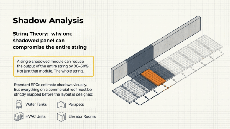
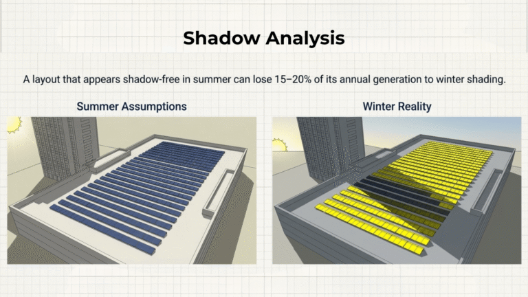
Shade is not just an inconvenience in solar. In the way most rooftop systems are wired, panels connected in series strings, shade on one panel pulls down the output of every other panel in that string. A single shaded module in a ten-panel string can reduce the output of the entire string by 30–50%. Not just that module. The whole string.
This is why shadow sources must be identified and modelled, not just estimated, before the layout is designed.
Everything on and around the roof must be mapped: water tanks, parapet walls, AC outdoor units, ventilation shafts, elevator machine rooms, mobile towers, neighbouring buildings, trees, and overhead lines. The height and position of each obstacle must be recorded precisely, because the shadow it casts changes with the time of day and the season. A layout that looks shadow-free in summer can lose 15–20% of its annual generation to winter shading.
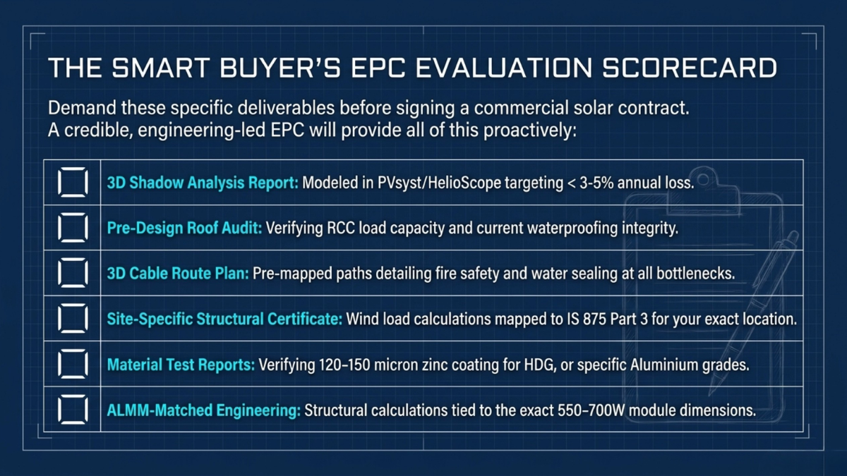
Professional shadow analysis uses 3D modelling software, like PVsyst or HelioScope, to simulate year-round shading loss for every proposed panel position. The target is to keep total annual shading loss below 3–5%.
When this step is skipped, the shading losses are not discovered later — they are simply silently embedded into the plant’s performance from Day 1.
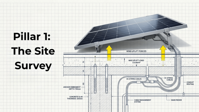
Before any solar structure is designed, the roof it will sit on must be assessed for two things: its capacity to carry the additional load, and its current physical condition.
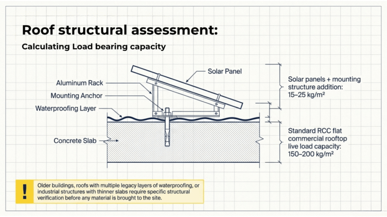
A standard RCC flat commercial rooftop is designed for 150–200 kg per square metre of live load. Solar panels and their mounting structure add roughly 15–25 kg/m². But older buildings, buildings with multiple layers of waterproofing that have added cumulative weight over the years, or industrial structures with thinner slab designs, need specific verification.
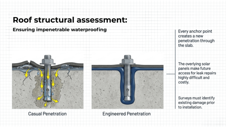
Waterproofing condition is another key part of the roof assessment. If the existing waterproofing is cracked, bubbling, or already showing early signs of leakage, installing a solar plant on top of it does not fix the waterproofing. It makes it far more expensive to fix later, because every anchor point you install creates a new penetration through the slab, and the panels now covering the roof make access for repairs difficult and costly.
A professional survey identifies waterproofing issues before installation begins, and advises the client as per the real ground situation.
Cable routing on a rooftop in a commercial building is a three-dimensional puzzle with physical obstacles at every turn.
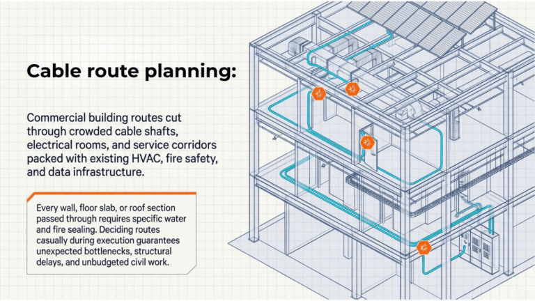
The DC cables from the panels must safely reach the inverter, and the AC power must then travel through the building to the main electrical panel. In a commercial facility, this path usually cuts through crowded cable shafts, electrical rooms, false ceilings, and service corridors already packed with existing electrical, HVAC, fire safety, and data infrastructure.
This is why cable route planning matters far more than most clients realize.
Every wall, floor slab, or roof section that the cable passes through needs to be properly sealed for water protection and fire safety. These points cannot be decided casually during installation. They must be identified during the engineering survey itself. The biggest risk is discovering a “bottleneck” after work has started, as they lead to delays, redesigns, extra civil work, and unexpected costs.
If this cable route planning is missing from the proposal, the project is still carrying unknown execution risks.
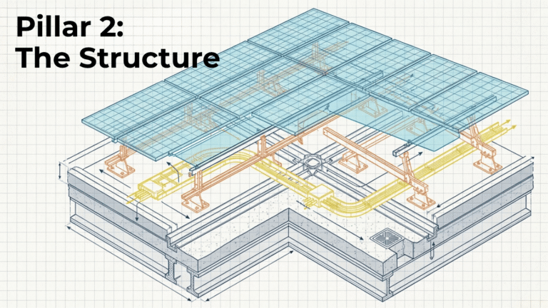
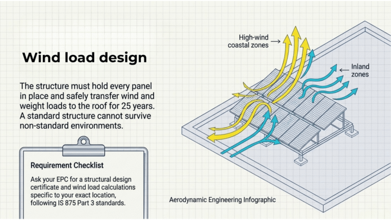
The mounting structure is one of the most important parts of a solar plant, even though most people never notice it once the installation is complete. It holds every panel in place, carries wind and weight loads safely to the roof, and must continue doing that reliably for 25 years. Unfortunately, it is also one of the first places where low-cost projects cut corners. Because structures degrade slowly, the connection between the original engineering decision and the later failure is rarely obvious.
A properly designed structure is not the same for every project. Wind conditions in coastal Gujarat or Tamil Nadu are very different from those in Rajasthan or Uttar Pradesh. That is why structural design must follow location-specific wind calculations under Indian standards like IS 875 Part 3. A “standard structure” used across all projects is not engineering; it is guesswork.
When reviewing a solar proposal, ask specifically: “Can you provide a wind load calculation and structural design certificate specific to my project location?” A credible engineering-led company provides a structural design certificate and wind load calculations specific to your site, which shows how the plant has been engineered for your building, location, terrain, and installation height.
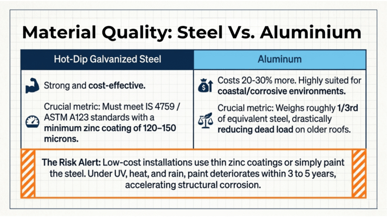
Material quality matters just as much. Most structures use either hot-dip galvanized steel or aluminium. Properly galvanized steel is strong and cost-effective, but only if the zinc coating meets required standards (IS 4759 and international equivalent ASTM A123 — specify a minimum coating thickness of 120–150 microns of zinc). Many low-cost installations use thinner coatings, or in some cases simply paint the steel rather than hot-dip galvanizing it. On a rooftop exposed to UV, heat, rain, and humidity, paint deteriorates within three to five years.
Aluminium costs more – roughly 20-30% more – but performs better in coastal or corrosive environments and also reduces roof load because it is much lighter (around 1/3rd of equivalent steel), which directly reduces the dead load on the roof slab, an important consideration for older buildings.
Even small details like nuts and bolts matter. Wrong fasteners can accelerate corrosion and weaken the structure over time. A reliable installer should be able to provide material test reports and galvanization certificates when asked.
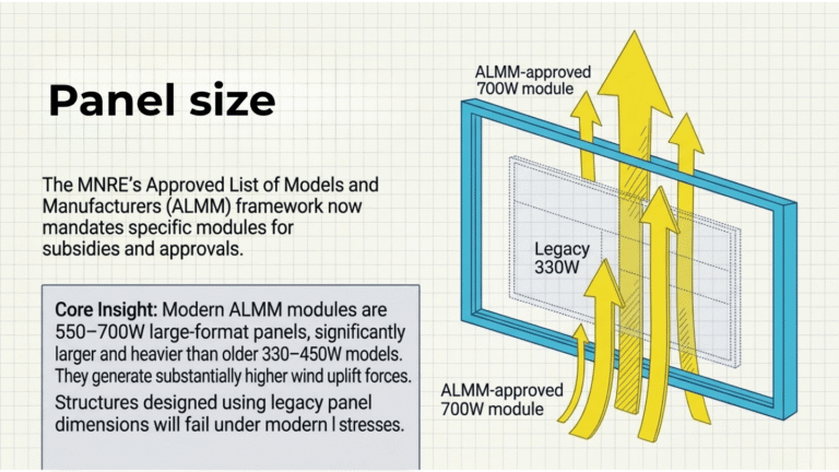
ALMM (Approved List of Models and Manufacturers) is the MNRE approval framework for solar modules and is mandatory to get subsidies, net metering, or government approvals. As of 2026, ALMM covers both the module and the solar cells inside it. EPC companies must manage compliance for both.
This also affects structural design because most ALMM-approved modules today are large-format 550–700W panels, compared to 330–450W a few years ago. These larger modules are heavier, bigger in size, and create higher wind uplift forces on the structure.
The structure must therefore be designed for the actual module dimensions, weight, and wind loading, not older panel formats. Before finalizing a project, ask for the exact module model being proposed, confirmation that it is ALMM-approved, and structural calculations based on that specific module size and weight
Most long-term solar losses happen in the electrical system. These problems are usually invisible at first, but over times they can result in signifiant generation loss. Some symptoms of poor electrical engineers are repeated inverter trips, erratic generation readings, error codes that the installer cannot explain. Electrical engineering of solar plants has many critical parts, below are ht e ones every decision makers must know about:
Panels connected in the same string should have the same wattage, voltage, and current characteristics. Mixing different modules, such as 330W and 545W panels, creates imbalance because the lowest-performing panel limits the output of the entire string.
Incorrect string design can also push the inverter outside its MPPT (Maximum Power Point Tracking) operating range, especially during temperature changes. On cold mornings, panel voltage rises, and poorly designed strings may cause inverter trips or shutdowns.
Every cable has resistance, and resistance causes power loss as heat. Undersized cables increase voltage drop, reduce efficiency, and run hotter over time. IEC 62548 recommends: maximum 3% voltage drop on the DC side and maximum 2% voltage drop on the AC side. The total should not exceed 5% (at Horizon, we ensure that the Voltage drop is kept under 4% at all times while doing the cable sizing/selection).
Even a few percent of avoidable loss becomes significant across a plant’s lifetime. Cable calculations should also account for rooftop temperatures, since cable resistance increases significantly in heat.
Solar DC cables are exposed to heat, UV radiation, rain, and moisture for decades. Proper solar cables should therefore include:
Using lower-grade cables may reduce upfront cost but increases long-term failure risk.
Earthing is not just a compliance formality. It protects people, equipment, and the building during electrical faults. Poor earthing is one of the most common reasons for inverter faults, unstable generation, and unexplained system trips in rooftop solar plants.
IS 3043, the Code of Practice for Earthing under the CEA (Central Electricity Authority) regulations for renewable energy installations also specify earthing requirements that must be met for grid interconnection approval. Broadly, this includes:
Surge Protection Devices (SPDs) protect the inverter and electrical system from lightning and sudden voltage spikes. Skipping SPDs to save cost can result in major equipment damage later. Surge Protection Devices (SPDs) must be installed at two points in the system:
The applicable standard is IEC 60364-5-53, which specifies Type 2 SPDs for photovoltaic systems. For larger installations, additional Type 1 SPDs at the main AC distribution point are recommended. Lightning protection for the structure itself comes under IEC 62305.
MC4 connectors are one of the most common failure points in solar systems. Poor-quality or incorrectly installed connectors create resistance, heat buildup, and sometimes fire risk.
A professional commissioning process should include:
These checks help detect poor connections before they become long-term failures.
A solar plant without proper documentation becomes difficult to maintain, troubleshoot, or expand later. A complete handover package should include:
|
Single-Line Diagram (SLD): |
The full electrical map of the system — showing strings, inverters, protection devices, and connections to the building panel. |
|
String layout drawing: |
Shows which rooftop panels belong to each electrical string, making fault detection and maintenance much faster. |
|
Cable schedule: |
Details cable type, size, length, and routing across the system. |
|
|
|
|
|
As-built drawings: |
Final updated drawings reflecting what was actually installed on site, including any changes during execution. |
|
Testing and commissioning reports: |
Includes insulation resistance tests, earth resistance measurements, string voltage readings, and thermal imaging (IR scan) results. |
|
Factory Test Reports (FTRs): |
Manufacturer test certificates for panels and inverters confirming equipment specifications. |
A solar plant without monitoring is a black box. You know how much electricity it generated last month. But you do not know if it was working at full capacity! You have no way of knowing if one string has been underperforming for three months or why your inverter keeps tripping. Without continuous monitoring you will only notice something is wrong when the problem has already cost you.
So, what should good monitoring look like? It should include:
Monitoring alone is not enough, regular maintenance is equally important.
A proper O&M (Operations & Maintenance) plan should include:
For commercial plants, at least one annual maintenance visit with thermal scanning and earthing checks should be standard. Larger or dust-heavy sites may need quarterly maintenance.
One important point to confirm before commissioning is inverter support:
Pillar | What You Should Ask | What a Good Answer Looks Like |
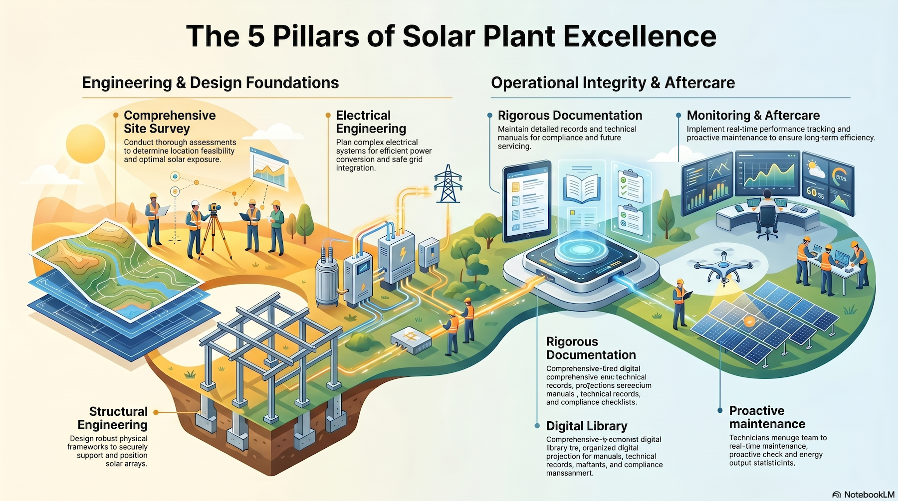
1. Survey & Planning | Is there a shadow analysis and cable route plan? | A proper 3D shadow analysis showing annual shading loss for your site, plus a documented cable route from rooftop panels to the distribution board with penetration points identified. |
2. Structure Design | Is the structure designed for my exact location? | Wind load calculations and a signed design certificate as per IS 875 Part 3, galvanization of at least 120 microns, and confirmation that the structure matches the actual module size being installed. Also verify ALMM compliance (List I & II). |
3. Electrical Engineering | What are the voltage drop calculations and testing standards? | Voltage drop within IEC 62548 limits (3% DC, 2% AC), calculated for real rooftop temperatures. Commissioning should include insulation testing, earth resistance below 1 ohm, string testing, and thermal imaging (IR scan). |
4. Documentation | What documents will I receive at handover? | SLD, string layout, cable schedule, structural drawings, earthing layout, as-built drawings, commissioning reports, and factory test reports for modules and inverters. |
5. Monitoring & O&M | Who manages the plant after commissioning? | String-level monitoring, remote alerts, defined O&M support, inverter warranty registration, and a clear local service contact. |
There are two ways to build a solar plant.
One treats it like a commodity: put panels on a roof, wire it up, connect it to the grid. That version is available at very low ₹/W prices, and it looks like solar on Day 1. But it also looks like year 3, when the inverter is tripping twice a day, the cable conduits are cracking, and no one can find the string layout drawing to figure out the problem.
The other handles it like a long term asset. It is built with proper engineering at every stage: structural design, cable sizing, earthing, surge protection, testing, documentation, and long-term monitoring. It may cost slightly more upfront, but it performs reliably for 25 years.
The difference is not luck. It is engineering discipline.
At Horizon Renewable Power, we provide the latter. We never compromise on quality and precision engineering. If you are evaluating a new solar installation or trying to understand why an existing system is underperforming, we would be glad to help you assess it properly.
If you’re thinking about solar not just as a project, but as a long-term capability, it’s worth starting that conversation early.